Anatomy of a Canal

Construction of the Delaware Division of the Pennsylvania Canal system began in 1827 and was completed by 1832. The quick work created a less than water-worthy structure and the canal quickly required additional funding and manpower to keep the boats afloat.
However leaky the original design, it included many features and mechanisms that can still be seen today. In fact, some are still in use.
From Bristol, the Delaware Canal rises 165 feet above sea level in Easton. This elevation change was overcome using 23 lift locks. Other structures along the canal included: 10 aqueducts, 21 waste gates, 8 stop gates, 27 overflows, 125 bridges, 1 weigh lock at Easton, 1 outlet lock and 1 tide lock. With careful restoration, preservation and maintenance locks, waste gates, and bridges add to the historic value of this natural resource.
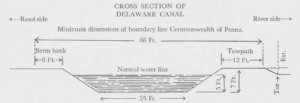
The canal structure itself is called the prism. Its name comes from the shape, being narrower on the bottom and wider on top, creating a “prism.” The bed of the canal was generally lined with clay, but in the haste of construction, other more porous materials were put to use.
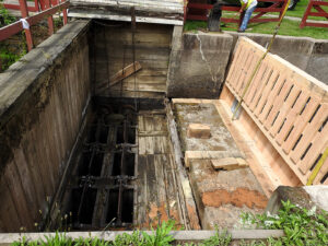
Waste gates and stop gates may sound similar but they serve two different functions. Waste gates are used to lower the water level in the canal (eliminating extra or “waste” water). Stop gates are used to divert water back into the river, protecting the canal downstream from flooding. During times of torrential rains, these gates are vital to preserving not only the canal structure but neighboring property as well.

Overflows or spillways are also used to control the level of the canal. During the recent rainstorms and Ida, these spillways became so inundated with water, that pedestrians could not pass for fear of being swept away. On a normal day, bikers, hikers and walkers alike may get a bit wet but they can easily cross these concreate structures.
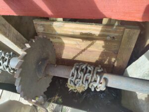
By far, the most complex mechanism along the canal is the lift lock. Locks are essentially elevators for canal boats. These enclosures were either filled with water or emptied, depending on whether the canal boat was traveling upstream (higher elevation) or downstream (lower elevation.) The lock chamber consisted of a floor, two walls and lock gates at either end. It was filled or emptied using openings in the lock gates, called wickets. (cont’d next page)
Steps to locking in when going downstream:
1. If the lock is empty, the lower miter gates are closed. The lock is then filled with water by opening the wickets (rotating valves) in the bottom section of the upper gates.
2. When the lock is full, the upper miter gates are opened, and the canal boat enters.
3. The wickets in the upper gates are shut, and the upper miter gates are fully closed.
4. The wickets in the lower gate are opened, and the level of the water in the lock is dropped until it is the same as the water level below the lock, lowering the boat.
5. When the water levels match, the lower miter gates are opened and the canal boat is pulled out of the lock and continues on its southward journey.
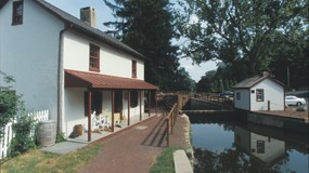
Lift locks have been in use for centuries in China as well as the Netherlands and Belgium. Variations of the standard lock can be found in the Theodore Roosevelt Recreation area, where two locks, Locks 22 and 23, were combined into one. At the beginning of the canal in the north, is a Weigh Lock in Easton. At the southernmost point along the canal is a Tidal Lock in Bristol.
Aqueducts are another important feature of the Delaware Canal. There are 10 aqueducts along the length of the waterway. Recent storm damage caused two of these structures to weaken or collapse entirely. Replacements and repairs are being planned for the aqueducts in Point Pleasant and Lumberville. When still in use as a transportation corridor, the aqueducts on the canal transversed streams carrying not only water but the boats as well. In later years, when commercial use stopped, these structures became a favorite watering hole of local bathers.


